A Short Guide on 8086 Architecture
Written by Antonius ( w1sd0m / ringlayer / sw0rdm4n )
https://www.bluedragonsec.com
https://github.com/bluedragonsecurity
The Interrupt
Interrupt is a mechanism that allow hardware or software to suspend normal execution on microprocessor in order to switch to interrupt service routine for hardware / software. Interrupt can also described as asynchronous electrical signal that sent to a microprocessor in order to stop current execution and switch to the execution signaled (depends on priority). Whether an interrupt is prioritized or not depends on the interrupt flag register which controlled by priority / programmable interrupt controller (PIC). There are 5 type of interrupts:
hardware interrupt, this is external interrupt caused by hardware; for example when pressing keyboard.
Non-maskable interrupt (NMI), the interrupt that can not be ignored by microprocessor.
Software interrupt, this is maskable interrupt that comes from a software; this interrupt comes when an assembly routine execute int instruction
Internal interrupt, this interrupt is a result of processor state violation, for example : divide by zero error
Reset, this interrupt will reset cpu state
Interrupt Vector Table (IVT) on 8086
Interrupt vector table on 8086 is a vector that consists of 256 total interrupts placed at first 1 kb of memory from 0000h to 03ffh, where each vector consists of segment and offset as a lookup or jump table to memory address of bios interrupt service routine (f000h to ffffh) or dos interrupt service routine address, the call to interrupt service routine is similar to far procedure call. The size for each interrupt vector is 4 bytes (2 word in 16 bit), where 2 bytes (1 word) for segment and 2 bytes for offset of interrupt service routine address. So it takes 1024 bytes (1 kb) memory for interrupt vector table. On 8086 with dos operating system, interrupt vector table at 00h-1fh (int num 0–31) consists of lookup / jump table address to hardware or bios interrupt handler routine, meanwhile 20h-ffh (int num 32–255) consist of jump table address to dos interrupt handler routine. For example int 13h that located on ivt at 0000:004c contains address of Bios ROM Interrupt Service Routine, what it records is segment F000h, and offset 1140h, each bytes of that address will be placed little endian. The lower the interrupt number on interrupt vector table means the more priority needed for an interrupt.
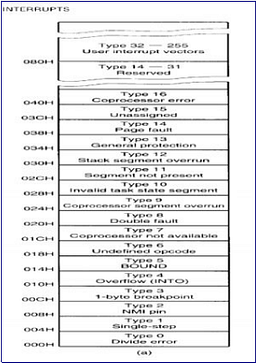
Below is example of bios interrupt declaration from bios source code at 8086tiny bios source code:
; Interrupt vector table - to copy to 0:0
int_table dw int0
dw 0xf000
dw int1
dw 0xf000
dw int2
dw 0xf000
dw int3
dw 0xf000
dw int4
dw 0xf000
dw int5
dw 0xf000
dw int6
dw 0xf000
dw int7
dw 0xf000
dw int8
dw 0xf000
dw int9
dw 0xf000
dw inta
dw 0xf000
dw intb
dw 0xf000
dw intc
dw 0xf000
dw intd
dw 0xf000
dw inte
dw 0xf000
dw intf
dw 0xf000
dw int10dw 0xf000
dw int11
dw 0xf000
dw int12
dw 0xf000
dw int13
dw 0xf000
dw int14
dw 0xf000
dw int15
dw 0xf000
dw int16
dw 0xf000
dw int17
dw 0xf000
dw int18
dw 0xf000
dw int19
dw 0xf000
dw int1a
dw 0xf000
dw int1b
dw 0xf000
dw int1c
dw 0xf000
dw int1d
dw 0xf000
dw int1e
On boot, interrupt vector table initialized by bios on rom, then interrupt vector table loaded to RAM.
Microprocessor get correponding entry on interrupt vector table by multiplying interrupt number with 4h. For example if int 16h called : 16 * 4 = 58h. Corresponding logical address that contains
address of rom bios routine for int num 4h will be on 0000h:0058h.
Interrupt Mechanism
For an example, an interrupt signal to processor may be signaled from a keyboard press. The interrupt signal then will be send via system bus to priority / programmable logic controller (example of commonly used pic on 8086 architecture is 8259a PIC). PIC will determine whether imr (interrupt mask register) is masked or not, if imr sets to 1,irq will not be send to processor otherwise if imr sets to 0, PIC will determine the priority of interrupt by checking interrupt service register (ISR) , where the lower interrupt number the higher the priority, once sequences completed, irq will be send to processor.
If interrupt flag on microprocessor sets to 0, processor will ignored the incoming interrupt signal. But if interrupt flag on microprocessor sets to 1, once interupt signal received by processor, microprocessor will stop current execution.
Microprocessor then will saves flag registers, then push
address of next execution counter (cs:ip) on the stack for later return. Microprocessor then will send ack to PIC, the PIC then send interrupt number to processor, This number then will be multiplied by
4 as offset address of the interrupt vector table. Microprocessor then will do a lookup to find a corresponding segment (cs) address and offset (ip)
address of isr address from interrupt vector table, once found, processor will sets interrupt flag to 0(disable interrupt) then both segment and offset address of interrupt service routine which taken from interrupt vector table will be put on cs:ip, where cs is the segment address of interrupt service routine (ISR) and ip (instruction pointer) will be offset address of interrupt service routine, then processor begins executing routines from interrupt service routine (similar to far call).
After interrupt service routine / interrupt handler routine executed, processor will pop back cs and ip then pop back flag register on the stack, then micropocessor will return to address that previously saved on the stack which now on cs:ip.
Another example of mechanism from the software point of view is when an assembly program execute int 13h function 1h (get recent disk status operation). The processor will record flag register and program counter for return address onto the stack, where this will be used for iret instruction in order to go back to next software routine after interrupt routine instruction completed.
The next execution of processor will lookup corresponding entry for interrupt number 13h on interrupt vector table. As already mentioned before offset address on interrupt vector table is interrupt number multiplied with 4 : 13h * 4h = 4ch = 0000:004c (0000:004c on ivt contains logical address of interrupt 13h ISR address).
Once the entry found, where it contains of 1 word segment (cs) and 1 word offset (ip) of bios rom routine address for interrupt 13h disk service it will be loaded to cs and ip.
Based on the calculation cs will be and ip will be taken from rom bios address that recorder on interrupt vector table address at 0000:004c. Then the execution will be driven (far call) to absolute address of bios rom routine that handle int 13h function 1h, for example here is a sample of bios routine that handle int 13h function 0h for disk reset (8086tiny bios source code):
int13:
cmp
ah, 0x00 ; Reset disk
je
int13_reset_disk
cmp
ah, 0x01 ; Get last status
je
int13_last_status
-------cutted-----------
int13_last_status:
mov
ah, [cs:disk_laststatus]
je
ls_no_error
stc ; set carry flag
iret
ls_no_error:
clc
iret
Once an assembly program call int 13h , microprocessor will save flag register and program counter (address of current execution), microprocessor then do a lookup to find corresponding entry
for “int 13h” on interrupt vector table.
Once corresponding entry found, it will jump to corresponding int 13h bios label (far call), since we use function 1h the next instruction will jump to int13_last_status label.
On int13_last_status label we see instruction : “mov ah, [cs:disk_laststatus]” this will move byte at address that pointed by cs:disk_laststatus. Absolute address of cs:disk_laststatus contains byte of bios disk error code, if it’s 0 means no error, rather than 0 means there’s an error of recent disk operation.
If ah = 0 then instruction clear carry flag before iret will be executed, but if error found, the next instruction will set carry flag before iret.
Once iret executed the instruction will then be returned back to next routine of assembly program that calls int 13h.
Another example is when int 21h function 2a being called, when microprocessor determine that the interrupt is prioritize rather than current execution, microprocessor will save flag register, program
counter onto stack. Once more, microprocessor will have a lookup on interrupt vector table.
As previous, logical address of int 21h on interrupt vector table can be found on interrupt vector table offset 0084h. We got IVT offset by multiplying interrupt number with 4. For interrupt 21h, the
calculation to get interrupt vector address is : “21h * 4h = 84h = 0000h:0084h”.
So entry for int 21h ISR address from interrupt vector table is located at logical address 0000:00084h.
Microprocessor will do a far call to interrupt service routine address, where it the address is recorded at interrupt vector table logical address at 0000h:0084h. For example here on ms dos 2:
procedure $GET_DATE,NEAR ;System call 42
ASSUME DS:NOTHING,ES:NOTHING
; Inputs:
; None
; Function:
; Return current date
; Returns:
; Date in CX:DX
PUSH SS
POP DS
ASSUME DS:DOSGROUP
invoke READTIME ;Check for rollover to next day MOV AX,[YEAR]
MOV BX,WORD PTR [DAY]
invoke get_user_stack ;Get pointer to user registers ASSUME DS:NOTHING
MOV [SI.user_DX],BX ;DH=month, DL=day ADD AX,1980 ;Put bias back
MOV [SI.user_CX],AX ;CX=year MOV AL,BYTE PTR [WEEKDAY]
RET
$GET_DATE ENDP
Once return :
AL = day of the week (0=Sunday)
CX = year (1980–2099)
DH = month (1–12)
DL = day (1–31)
After interrupt execution completed (right after iret), the processor will back to next instruction which recorded on stack before by pop it back to cs and ip (previously, the next instruction is suspended when microprocessor receives irq from pic).
Some Bios (Basic Input Output System) Interrupts
Below is some examples of bios interrupt and it’s usage. We do not provide complete list here, since the purpose just for understanding bios interrupt usage.
int 10h
int 10h handling routine was provided by bios, this interrupt is used for video mode operations. Example : int 10h function 00h.
This is for setting video mode. requirement :
ah = video mode
al = 00h
Example usage of int 10h function 00h:
;10_0.asm
;int 10h function 00h demo
;this is for setting video mode
;made by Antonius (sw0rdm4n)
;http://www.ringlayer.net
;compile with tasm 2.0 and tlink 3.0
;tasm 10_0.asm
;tlink /t 10_0.obj
.model tiny
.data
strx db 'h4x0r$'
.code org 100h
start:
mov al, 00h; set video mode 40 x 25 resolution call _uber
mov al, 02h; set video mode 80 x 25 resolution call _uber
mov al, 06h; set video mode 640 x 200 resolution call _uber
mov al, 13h; set video mode vga 640 x 480 resolution call _uber
int 20h
_uber proc near
call _setvideo
call _printf
call _wait
retn
_uber endp
_printf proc near
mov dx, offset strx
mov ah, 09h
int 21h
retn
_printf endp
_wait proc near
mov ah,00h
int 16h
retn
_wait endp
_setvideo proc near
mov ah,00h
int 10h retn
_setvideo endp
end start
int 12h
int 12h used to get memory size. This interrupt will returns the contents of the word at segment 0040h and offset 0013h into ax register.
Example code:
;memory.asm
;get memory size
;returns the contents of the word at segment 0040h and offset 0013h into ax register
;made by Antonius (@sw0rdm4n)
;http://www.ringlayer.net
.model tiny
.data
_mem dw 00
.code
org 100h
start:
xor ax,ax
int 12h
nop
int 20h
end start
Assemble : tasm memory.asm , link : tlink /t memory.obj, then debug “memory.com”
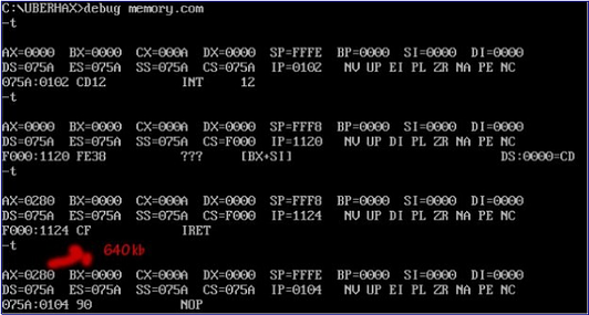
we can see right after iret from bios routine executed, register ax will contains 1 word: 0280. Dump memory content at 0040:0013 :

We can see it contains bytes in little endian order : 80 02, in non little endian = 0280h , in decimal = 640. So we got 640kb memory size.
Some DOS Interrupts
Dos interrupt is interrupt routines provided by dos, on interrupt vector table 20h-3fh is dos vector interrupt. Below is some of dos interrupt (we do not give complete lists)
int 21h
int 21h is dos function codes, provided by dos operating system.
example : “int 21h function 35h”, this interrupt function is used to get address of interrupt service routine where it’s recorded at interrupt vector table.
requirements:
ah = 35h
al = interrupt number
After int 21h function 35h executed, es (extra segment 16 bit) register will be segment address of ISR and bx (base register 16 bit) register will be offset address of ISR.
Example code that uses int 21h function 35h:
;getivt.asm
;simple routine to get interrupt vector table content
;segment of isr will be saved to es register
;offset of isr will be saved to bx register
;compile :
;tasm getivt.asm
;tlink /t getivt.obj
;programmer : Antonius (sw0rdm4n)
;http://www.ringlayer.net
.model tiny
.data
.code start:
_segment dw 0000h
_offset dw 0000h
org 100h
mov bl,13h ; get bios rom routine address for int 13h
call _get_ivt
nop
nop
call _cleanres
mov bl, 21h ; get os routine address for int 21h
call _get_ivt
nop
nop
call _cleanres
mov bl, 10h ; get bios rom routine address for int 10h
call _get_ivt
nop
nop
call _cleanres
int 20h; ret to dos
_cleanres proc near
xor bx, bx
ret
_cleanres endp
_get_ivt proc near
mov ah,35h
mov al, bl
int 21h
retn
_get_ivt endp
end start
Let’s see what above routines executed in background. Compile using tasm 2.0 and tlink 3.0:
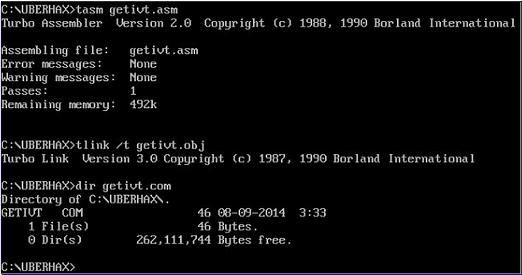
Debug it using debug.exe : “debug getivt.com” then stepping by type : “t” then enter until the first int 21h executed:
Press enter or click to view image in full size
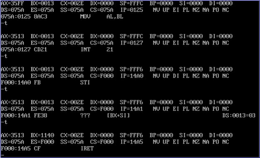
We can see that bx contains offset of address of int 13h routine provided from rom bios (on RAM) : 1140h. Meanwhile es contains segment address of bios routine that serve int 13h : f000h.
So bios routine that provides ISR for interrupt 13h starts from address f000h:1140h. On interrupt vector table int 13h can be lookup on 0000:004c (13h * 4h = 4ch).
To dump memory content at 0000:004c we type: “d 0000:004c l 4” means we wish to dump 4 bytes from memory at segment 0000h offset 004ch.
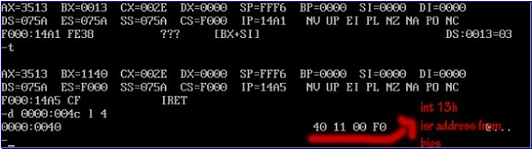
We can see on 0000:004c contains 1 word for segment and 1 word for offset address of interrupt service routine for int 13h, which encoded using little endian order : 1 word (2 bytes) for offset : 40 11 and 1 word (2 bytes) for segment : 00 f0. Where if encoded to non little endian offset = 1140h and if segment encoded to non little endian = f000h. We’ve cross checked that isr address of 13h handle routine mapped at address f000:1140.
int 21h function 2ah
This interrupt used to get system date, once iret of isr executed, cx will contains year, dh contains month,dl contains day. This routine mostly abused for time bomb virus in past time.
Example code:
;date.asm
;once iret of isr executed,
;cx will contains year
;dh contains month
;dl contains day
;coded 8 Sept 2014
;by sw0rdm4n
.model tiny
.data
_timebomb_year dw 07deh
_timebomb_month db 09h
_timebomb_day db 08h
_timebomb_msg db "AlexanderPD timebomb start - I'm sorry sir !", 13,10,
'$'
.code
org 100h
start:
mov ah, 2ah
int 21h
_timing_bomb_check:
cmp cx, _timebomb_year
je _check_month
int 20h
_check_month:
cmp dh,_timebomb_month
je _check_day
int 20h
_check_day:
cmp dl, _timebomb_day
je _timebomb_joke
int 20h
_timebomb_joke:
call _setvid
mov ah, 09h
mov dx, offset _timebomb_msg
int 21h
int 20h_setvid proc near
mov al, 0h
mov ah,00h
int 10h
ret
_setvid endp
end start
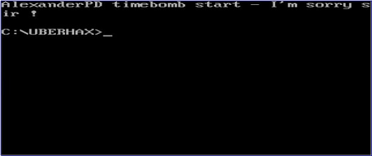
Every time this code executed on 8 Sept 2014, a joke message will be displayed:
8086 Addressing Modes
It’s very important to understand addressing mode before understanding instruction sets. Here we provide several data addressing mode examples.
What we given here is not a complete list, since the purpose is just for understanding x86 instruction syntaxs:
Immediate Addressing Mode
Direct Offset / Displacement Addressing Mode
Register Direct Addressing Mode
Register Indirect Addressing Mode
Indexed Addressing Mode
Base Index Addressing Mode
Base Index and Displacement Data Addressing Mode
Immediate Addressing Mode
Using immediate addressing mode means the data or operand immediately included in instruction. Examples:
mov ax,0h
mov al, 1b
mov ah, 1b
For example “mov ax, 11b” will move immediate value : 11 binary to ax register, those 2 bit will be moved to al register. So basically it’s the same instruction as “mov al, 11b”.
Before mov on 8 bit register al, when ah = 0h and al = 0h ,
before mov ax,11b :
al 8 bit register:
[0][0][0][0][0][0][0][0]
After mov ax,11b:
al 8 bit register:
[0][0][0][0][0][0][1][1]
Another example when ah = 0h and al=0h : “mov ax, 100h”. Since 100h in binary is “100000000b” it will overflow 8 bit register al, hence the first bit : “1b” will be placed on ah register.
Before mov ax,100h :
al (accumulator low) 8 bit register : [0][0][0][0][0][0][0][0]
ah (accumulator high) 8 bit register: [0][0][0][0][0][0][0][0]
After "mov ax, 100h" :
al (accumulator low) 8 bit register : [0][0][0][0][0][0][0][0]
ah (accumulator high) 8 bit register: [0][0][0][0][0][0][0][1]
Direct Offset / Displacement Addressing Mode
Using direct addressing, we directly load an offset address of variable to a register. Example:
mov dx, ds:[10ah]
mov dx, offset variable
For example:
.model tiny
.data
hax db 'h4x0r$'
.code org
100h
start:
mov dx, offset hax; -> direct offset address addressing
mov ah, 9h
int 21h
int 20h
end start
Using direct offset addressing, we directly put offset address of string hax to dx register.
The rule is that if no segment register specified, default segment register that will be used is ds, and as any other transfer instruction operand’ maximal size is size of destination.
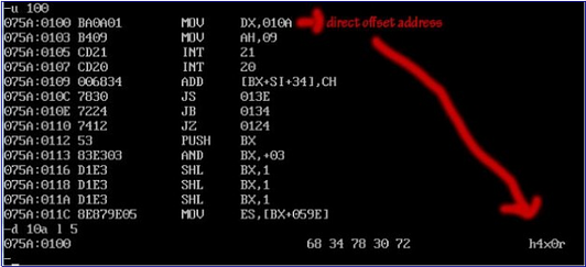
We can see we directly transfer offset address of hax string which at offset address 10ah to dx register, if we dump 10ah about 5 bytes we can see it contains string “h4x0r” which previously defined before.
We can also use memory address as displacement (on masm we use disp keyword, in this example we use tasm without disp keyword):
;displacement mode sample
;simple code by : Antonius (sw0rdm4n)
;www.ringlayer.net
.model tiny
.data
binx db 41h
.code
org 100h
start:
mov ah,2h
mov dx, ds:[10ah]
int 21h
int 20h
end start
“mov dx, ds:[10ah]” will move byte at address ds:10ah to register dx.
Register Direct Addressing Mode
Direct register addressing mode will use directly content of an operand register. Examples:
mov ax, bx; move bytes content of bx register to ax register
mov dl,al; move bytes content of al register to dl register
The rule is register size must be the same. If source is 8 bit regsiter, destination must be also 8 bit
register. You won’t put operand size larger than destination register.
Register Indirect Data Addressing Mode
Using register indirect addressing to access data means we use a register as a pointer to a memory address contains specific bytes.
Examples:
mov dx, [bx]
mov dx, cs:[bx] ; for different code segment
For example once instruction “mov dx, [bx]” executed, what happens is microprocessor will check offset address that is in bx register, for example bx register contains : “10e”.
Microprocessor will suppose it as an offset address, Microprocessor then will fetch 2 bytes on offset 10eh and move it to dx register.
Example code:
;indirect register example
;made by sw0rdm4n
;www.ringlayer.net
.model tiny
.data
hax db 01000001b
.code
org 100h
start:
mov bx, 10eh
mov dx, [bx]
mov ah,02h
int 21h
mov dx, offset hax
int 20h
end start
Actually instruction “mov dx, offset hax” is a junk, this is just for debugging purpose, just like printf(on user space c codes) and printk (on kernel space c codes).
At first “mov bx, 10eh” this instruction will move 10eh. 10eh will be supposed as offset address of variable hax.
mov dx, [bx], in this instruction, processor will assume bx as offset address pointer. Next, microprocessor will check offset address that recorded on bx register, within next sequece, microprocessor will get 2 bytes from 10eh and move it to dx register.
Indexed Addressing Mode
This mode uses special purpose index register such as si and di.
Examples:
call cs:[di]
add byte ptr cs:[di], 1b
mov bx, cs:[si]
mov al, byte ptr cs:[di]
mov byte ptr cs:[di], al
mov byte ptr cs:[di], 1b
and byte ptr cs:[si], 11111111b
The possible combinations :
cs: |
ds: | si / di ss: |
es: |
If no segment register specified, by default ds will be used. Example
code:
;simple index addresing mode example
;made by Antonius (@sw0rdm4n)
;http://ringlayer.net
;compile with tasm 2.0 and tlink 3.0
.model tiny
.datasayhawatpu db 73h,61h,79h,68h,61h,77h,61h,74h,70h,75h ; string
sayhawatpu
indexme db 10 dup (?)
.code org
100h
main:
mov si, offset sayhawatpu
xor cx, cx
call _setvid
looper:
mov bl, byte ptr cs:[si]; indexed addressing mode example
mov byte ptr[indexme], bl
mov dl, byte ptr[indexme]
call _printout
inc cx
inc si
cmp cx, 1010b
jl looper
int 20h
_printout proc near
mov ah, 2h
int 21h ret
_printout endp
_setvid proc near
mov al, 0h
mov ah,00h
int 10h ret
_setvid endp
end main
On routine : “mov bl, byte ptr cs:[si]” it will move byte that pointed by offset address which recorded in source index.
What above codes did is simple, just print string “sayhawatpu” in vga video mode.

Base Index and Displacement Data Addressing Mode
This mode is combination of indexed, base and displacement data addressing mode.
Displacement can be 8 bit or 16 bit depends on the size of destination and purpose of routine.
The possible combinations :
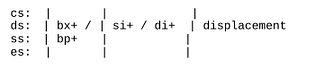
Examples:
mov dl, [bp + si + 1]
mov dx, [bx + si + 10h]
Example code:
;simple base and index addresing with displacement example
;made by Antonius (@sw0rdm4n)
.model tiny
.data
ibmbio db 68h,61h,78h ; hax
indexme db 3 dup (?)
.code
org 100h
main:
mov si, offset ibmbio
call _setvid
mov bp, 0h
mov bl, byte ptr cs:[bp + si + 0h]; base indexed + displacement example
mov byte ptr[indexme], bl
mov dl, byte ptr[indexme]
call _printout
mov bp, 1h
mov bl, byte ptr cs:[bp + si + 0h]; base indexed + displacement example
mov byte ptr[indexme], bl
mov dl, byte ptr[indexme]
call _printout
mov bp, 0h
mov bl, byte ptr cs:[bp + si + 2h]; base indexed + displacement example
mov byte ptr[indexme], bl
mov dl, byte ptr[indexme]
call _printout
int 20h
_printout proc near
mov ah, 2h
int 21h ret
_printout endp
_setvid proc near
mov al, 13h
mov ah,00h
int 10h
ret
_setvid endp
end main
For example on this routine :”mov bl, byte ptr cs:[bp + si + 2h]” , this means to move a byte that’s located from offset address calculation of bp + si + 2h
I think that’s enough guide. Thank you
Visit our web : www.bluedragonsec.com
Github : https://github.com/bluedragonsecurity
